
14.2.2 To Make a Diagnosis1 Timer LED starts to blink and the unit automatically stops the operation.
2 Press the CHECK button on the remote control continuously for 5 seconds.
3 "- -" will be displayed on the remote control display.
Note: Display only for "- -" (No signal transmission, no receiving sound and no Power LED blinking)
4 Press the TIMER ? or ? button on the remote control. The code "H00" (no abnormality) will be displayed
and signal will be transmit to the main unit.
5 Each press of the button (? or ?) will increase error code
number and transmit error code signal to the main unit.
6 When the latest abnormality code on the main unit and
code transmitted from the remote control are matched,
Power LED will light up for 30 seconds and a "beep" sound
(continuously for 4 seconds) will be heard. If no codes are
matched, Power LED will light up for 0.5 seconds and no
sound will be heard.
7 The breakdown diagnosis mode will be canceled unless
pressing the CHECK button continuously for 5 seconds or
operating the unit for 30 seconds.
8 The LED will be off if the unit is turned off or the RESET
button on the main unit is pressed.
Diagnosis
display
Abnormality / Protection control
Abnormality
Judgement
Emergency operation
Primary location to verify
H00
No abnormality detected
-
Normal operation
H11
Indoor / Outdoor abnormal communica
tion
> 1 min after starting
operation
Indoor fan operation
only
• Internal / external cable connections
• Indoor / Outdoor PCB
H14
Indoor intake air temperature sensor
abnormality
Continue for 5 sec.
-
• Intake air temperature sensor (detec
tive or disconnected)
H15
Outdoor compressor temperature sensor
abnormality
Continue for 5 sec.
-
• Compressor temperature sensor
(detective or disconnected)
H16
Outdoor Current Transformer open cir
cuit
-
-
• Outdoor PCB
• IPM (Power transistor) module
H19
Indoor fan motor mechanism locked
7 times occurance
continuously
-
• Indoor PCB
• Fan motor
H23
Indoor heat exchanger temperature sen
sor abnormality
Continue for 5 sec.
O
(Cooling only)
• Heat exchanger temperature sensor
(detective or disconnected)
H24
Indoor heat exchanger temperature sen
sor 2 abnormality
Continue for 5 sec.
-
• Heat exchanger temperature sensor
(detective or disconnected)
H27
Outdoor intake air temperature sensor
abnormality
Continue for 5 sec.
O
• Outdoor temperature sensor (detec
tive or disconnected)
H28
Outdoor heat exchanger temperature
sensor abnormality
Continue for 5 sec.
O
• Outdoor heat exchanger temperature
sensor (detective or disconnected)
H30
Outdoor discharge air temperature sen
sor abnormality
Continue for 5 sec.
-
• Outdoor temperature sensor (detec
tive or disconnected)
H33
Indoor / Outdoor wrong connection
-
-
• Indoor / Outdoor supply voltage
H38
Indoor / Outdoor mismatch (brand code)
H50
Ventilation motor abnormality
7 times occurance
continuously
-
• Indoor PCB
• Ventilation motor
H51
Nozzle lock abnormality
2 times occurance
continuously
-
• Nozzle
H52
Limit switch abnormality
-
-
• Indoor PCB
H97
Outdoor fan motor mechanism locked
2 times occurance
within 30 minutes
-
• Indoor PCB
• Fan motor
H98
Indoor high pressure protection
-
-
• Air filter dirty
• Air circulation short circuit
H99
Indoor heat exchanger anti-freezing pro
tection
-
-
• Insufficient refrigerant
• Air filter dirty
F11
Cooling / Heating cycle changeover
abnormality
4 times occurance
within 30 minutes
-
• 4-way valve
• V-coil
F90
PFC control
4 times occurance
within 10 minutes
-
• Voltage at PFC
F91
Refrigerantion cycle abnormality
2 times occurance
within 20 minutes
-
• No refrigerant
(3-way valve is closed)
F93
Compressor rotation failure
4 times occurance
within 20 minutes
-
• Compressor
F95
Cool high pressure protection
4 times occurance
within 20 minutes
-
• Outdoor refrigerant circuit
F96
IPM (power transistor) overheating pro
tection
4 times occurance
within 30 minutes
-
• Excess refrigerant
• Improper heat radiation
• IPM (Power transistor)
F97
Outdoor compressor overheating protec
tion
4 times occurance
within 10 minutes
-
• Insufficient refrigerant
• Compressor
F98
Total running current protection
3 times occurance
within 20 minutes
-
• Excess refrigerant
• Improper heat radiation
F99
Outdoor Direct Current (DC) peak detec
tion
7 times occurance
continuously
-
• Outdoor PCB
• IPM (Power transistor)
• Compressor
Note:
"O" - Frequency measured and fan speed fixed.
The memory data of error code is erased when the power supply is cut off, or press the Auto Switch until "beep" sound heard following by pressing the "CHECK" button at remote controller.
Although operation forced to stop when abnormality detected, emergency operation is possible for certain errors (refer to Error Codes Table) by using remote controller or Auto Switch at indoor unit. However, the remote controller signal receiving sound is changed from one "beep" to four "beep" sounds.
SOURCE: Panasonic Split System Air Conditioning.
we have a old national air con cassette model cu-5chv11p , works for three days , then controller comes on e4 error ,and then switches off , and will not reset .
SOURCE: Panasonic split system air con cs/cu-e24gkr
check the indoor unit sirkit board,there is problem.
SOURCE: Flap will not lift
Hi,
Either there is a problem with the circuit board or the little motor that runs the flap open and shut. The only way to tell would be to try and get a metter on the motor when it should be operating and find out if it is getting power. Look on the motor for the type of power and voltage. It may be like 12v DC.
To get cooling for now you can take off the cover and unhook the linkage that runs the flap and prop it open. Be careful as the linkage can be very fragile. And you want to take it apart is such a way so that you can reassemble it once you get the parts replaced.
Heatman101
SOURCE: Yonan Split Air Conditioning System
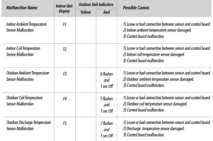
F6
ambient temp.
sensor of outdoor
fault
1?Check whether the resistance of sensor is normal,
otherwise replace it.
2?Check whether the sensor wire is short circuit or open
circuit, and whether the plug is well contacted, whether
there is welding off or rosin joint on the electric control
board, repair it if there is any above.
3?When the 1 and 2 are both normal, then the components
or integrated circuit is damaged, the electric control
board should be replaced.
3,464 views
Usually answered in minutes!


×